Oedometer soil test
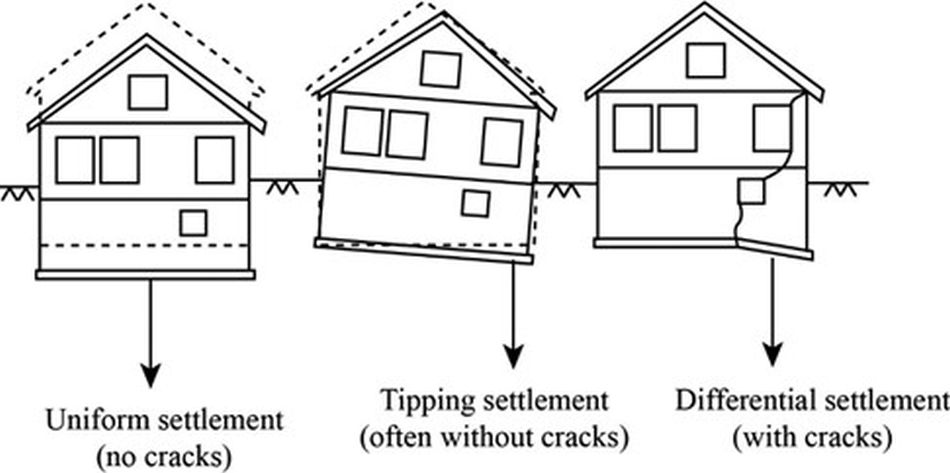
Predicting the settlements of structures is one of the most demanding problems faced by designers in geotechnics. Disregard and incorrect assumptions about foundation soil compressibility can lead to additional stresses within the structure and ultimately to its cracking and collapse.

Two components are most important to designers observing settlements:
- the value of the total settlements that will occur; and
- the time of realization of the total settlements.
These two components can be approximated based on the results of soil compressibility laboratory tests. In engineering practice, one of the most widely used laboratory devices for testing soil compressibility is the oedometer.
Oedometer
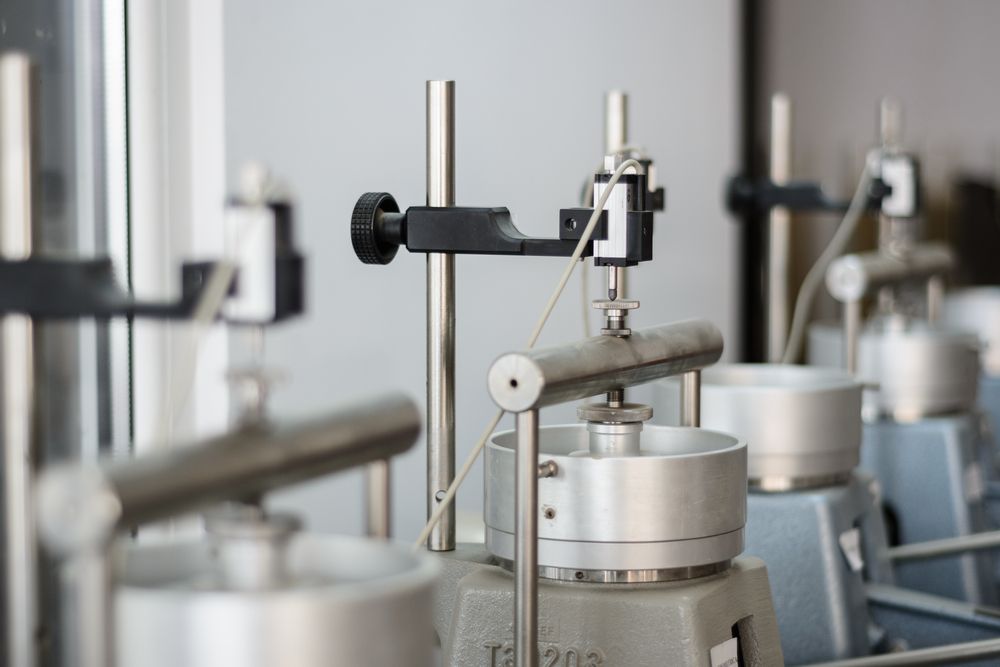
The oedometer is a laboratory device used for the examination of soil compressibility under a load and under conditions of prevented lateral strain in the soil. An undisturbed soil sample is installed for the test and then the initial height of the soil and the change in height due to load application are measured.

The basic parts of the oedometer are:
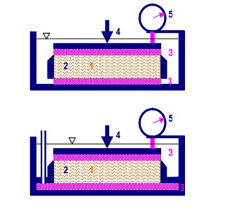
- an oedometer ring into which the undisturbed test specimen is fitted: the fitting of the specimen into the rigid ring prevents horizontal soil deformations during the test (2);
- two porous discs with filter paper that are placed below and above the sample fitted in the ring and allow drainage of the sample (3);
- a loading cap which is recessed at the top and placed on the upper porous discs so as to transfer the load over the entire horizontal surface of the sample uniformly in order to obtain uniform deformations of the sample (4);
- a loading frame. The load is most often applied via a piston on a loading cap, which is connected to the weight via a lever system, and can also be applied hydraulically;
- a deformation measurer (loading cap displacement sensor) for measuring sample deformation (5).
Oedometer test procedure
The oedometer test procedure is based on the measurement of the vertical displacement of the sample due to the application of a vertical load. An example of the procedure is given below.
– The soil sample is installed to allow water saturation.
– The position of the cap covering the sample is read.
– The first load increment is applied, most often over a weight that hangs on a lever and thus uniformly loads the entire sample.
– The position of the cap covering the sample is read again.
The presence of water in the soil pores slows down the deformation. The fastest changes occur immediately after the application of the load, and then slow down continuously. Typical read times of cap position change are after 4 s, 8 s, 15 s, 30 s, 1 min, 2 min, 5 min, 15 min, 45 min, 2 h, 4 h, 8 h, 24 h, 2 days, 3 days and so on until the deformation subsides. Once the deformation has subsided, the next degree of load is applied, usually twice as large as the previous one during loading or four times smaller than the previous one during unloading.
Oedometer test results
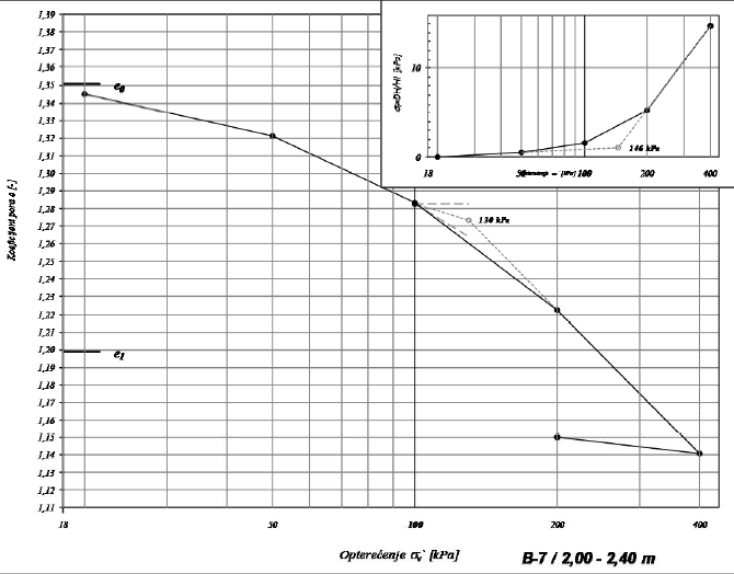
For each increase in the vertical loading, a curve of the change in the height of the sample over time in a semi-logarithmic scale is plotted. The ultimate goal is to gain insight into the change in sample volume with a change in vertical load with the help of measured vertical displacements. The change in the sample volume is shown by the change in the pore coefficient. The figure below shows the oedometer curve (curve of the change in the volume of the sample in relation to the change in loading).

Based on the ratio of the change in the pore coefficient with the change in the vertical stress (visible from the oedometer curve), the value of the compressibility coefficient of the soil sample (av) is obtained according to the following expression:

Using the compressibility coefficient (av) it is possible to determine the value of the modulus of change of the volume of the soil sample (mv):

Through the modulus of volume change (mv) it is easy to determine the modulus of compressibility of the soil (Ms) which represents the input data for the deformation behavior of the soil in most software packages for the analysis of soil-structure interaction. The connection between the modulus of compressibility and the modulus of volume change is shown below:

The modulus of compressibility of a particular soil type is not a constant value because it depends on a particular stress state for which a change in volume is observed. For this reason, the experiment needs to be performed for multiple ranges of vertical load change (e.g., 50–100 kPa → 100–200 kPa → 200–400 kPa). The maximum load ranges at which the soil sample is tested depend primarily on the depth of intervention for which the deformation characteristics of a particular soil layer are needed.
*References:
Jagodnik, V. (2017.): Eksperimentalna mehanika tla – skripta Građevinskog fakulteta Sveučilišta u Rijeci
Zlatović, S. (2001.): Mehanika tla – bilješke za predavanja; Tehničko veleučilište Zagreb
Nonveiller, E. (1990.) Mehanika tla i temeljenje građevina (III. izdanje); Školska knjiga, Zagreb.
Read more: Laboratory teststing, Differential settlements
