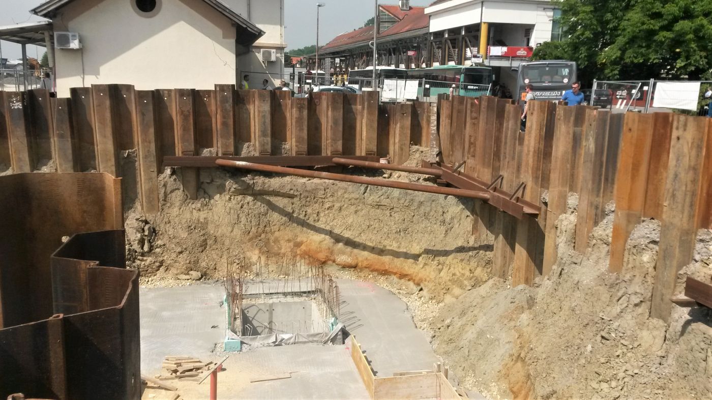
Prop loads in embedded retaining structures
There are two basic types of retaining structures: backfilled and embedded retaining structures. Backfilled retaining structures are gravity walls, reinforced concrete cantilever walls, gabion walls, reinforced soil structures. Embedded retaining structures are: diaphragm walls, pile walls and sheet pile walls.
For smaller open pit depths it is possible to use embedded retaining structures without additional protection (cantilever load transfer) but for larger depths, it is necessary to support the retaining structure with additional structural elements such as props, anchors or slabs of the future structure.
The increasing demand for underground constructions in urban areas highlights the need for achieving more economic design of retaining structures. The requirement of limiting ground movements and the need to ensure that no failure of the support system occurs is an important factor in design.
An embedded retaining structure must be designed in accordance with Eurocode 7 and the associated national annex.
Design methods
Different analysis methods are used for the design of the retaining structures and support system.
Limit equilibrium method
In limit equilibrium analysis the equilibrium of the wall is assessed under the action of assumed lateral pressure distributions, usually based on limiting (active and/or passive) lateral earth pressure coefficients. Limit equilibrium methods are directly applicable for some structures (cantilever walls) than others (multi-propped walls).
Subgrade reaction and pseudo-finite element methods
In the simplest soil
Finite element and finite difference methods
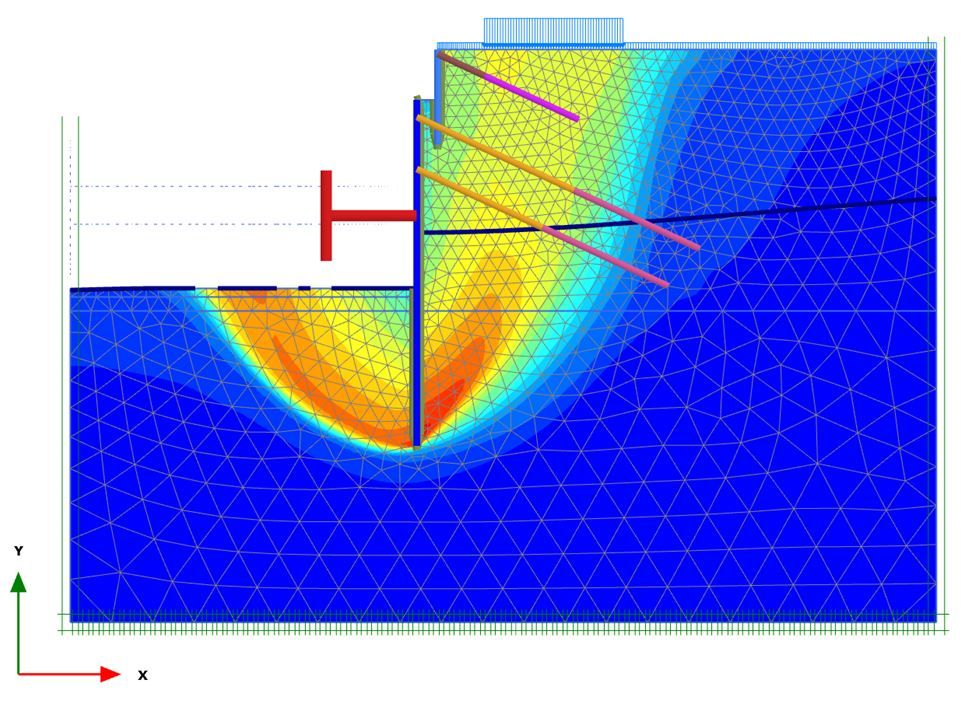
These soil-structure interaction analyses model the ground and the wall and its construction sequence, using a finite element or finite difference methods.
Ground movements, wall movements, bending moments and prop loads are calculated.
Empirical methods
Empirical methods have been used for embedded wall design and, in order to obtain the design prop forces for multi-propped walls. There are a
CIRIA C517 (Twine & Roscoe,1999), suggests the Distributed Prop Load method (DPL).
Similar guidance and empirical graphs exist in German Recommendations on Excavations: EAB, 3rd Edition, 2014.
Prop design load
The design load acting on the props will depend upon the analysis method adopted for the design of the wall. Prop loads calculated from limit equilibrium analysis may be unconservative, as the effects of soil-structure interaction are not included.
Soil structure interaction methods allow stress redistribution and provide more realistic values of prop loads. The calculated prop loads should be compared with those derived from comparable experience.
Ultimate limit state prop load (Ed) derived from the wall design calculations:
Ed = max (γG x PSLS x γsd ; PULS,d x γsd)
where
PSLS – serviceability limit state action derived from SSI analysis, limit equilibrium or distributed load method
G – factor for permanent
γsd – model factor for stress redistribution effects (1,0 for SSI analysis; 1,15 for limit equilibrium analysis)
PULS,d – maximum design effect of actions from ultimate limit state calculations (design approach 3)
Distributed prop load method (DPL method)
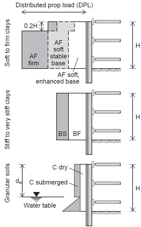
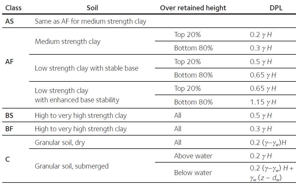
The DPL method for calculating prop loads for propped temporary excavations is based on the back analysis of field measurements of prop loads relating to 81 case studies, of which 60 are for flexible walls (steel sheet pile, king post walls) and 21 are for stiff walls (contiguous, secant, diaphragm walls). The case study data relate to excavations ranging in depth from 4 m to 27 m, typically 5 m to 15 m in soft and firm clays (soil class A), 10 m to 15 m in stiff and very stiff clays (soil class B) and 10 m to 20 m in coarse-grained soils (soil class C).
Distributed prop load diagrams for soil classes A to C are given for flexible (F) and stiff (S) walls.
Soil class:
A – normally and slightly overconsolidated clay soils (soft to firm clays)
B – heavily overconsolidated clay soils (stiff and very stiff clays)
C – coarse-grained soils
D – mixed soils (walls retaining both fine-grained and coarse-grained soils)
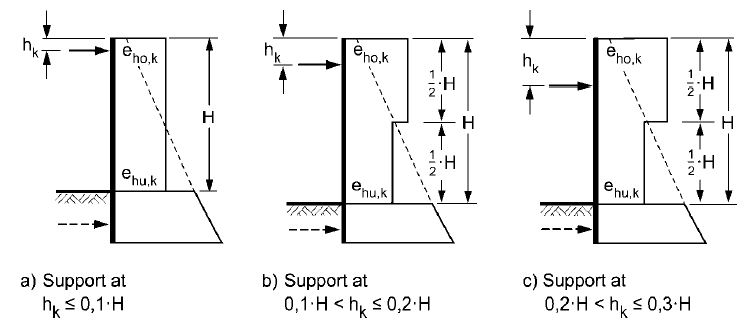
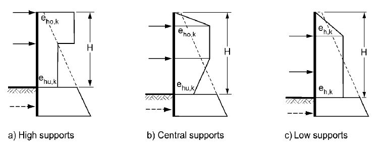
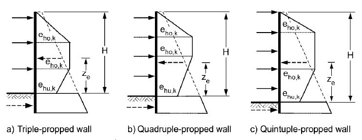
Pressure diagrams (EAB, 3rd Edition, 2014.)
The pressure diagrams bellow taken from German Recommendations on Excavations: EAB, 3rd Edition, 2014., assume earth pressure redistribution from the ground surface to the excavation level
The following pressure diagrams may be regarded as realistic for single propped walls:
The following pressure diagrams may be regarded as realistic for double propped walls:
The following pressure diagrams may be regarded as realistic for triple or multiple-propped walls:
Conclusion
Steel sections are commonly used for temporary props. The design load acting on the props will depend upon the analysis method adopted for the design of the wall. Soil structure interaction methods allow stress redistribution and provide more realistic values of prop loads. The calculated prop loads should be compared with those derived from comparable experience.
*References:
Arcelor Mittal Piling Handbook, 9th edition, 2016.
Gaba A., Hardy S., Doughty L., Powrie W., Selemetas D., Guidance on embedded retaining wall design, Ciria, 2017.
Katsigiannis G., Schweiger H., Ferreira P., Fuentes R., Design of Deep Supported Excavations: Comparison Between Numerical and empirical Methods, 2015.
Read more: Retaining structures
