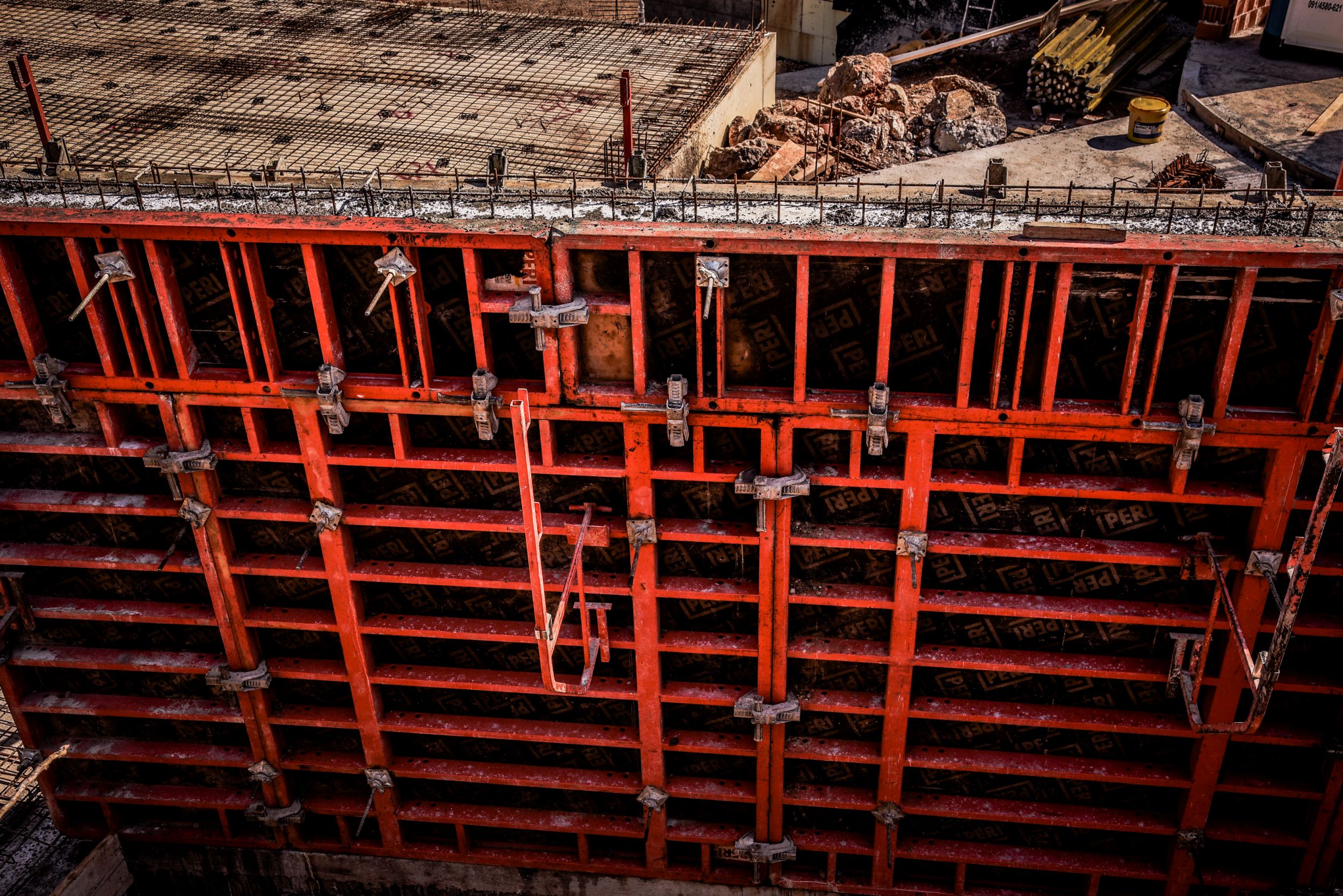
Selection of reinforced concrete retaining wall geometry
Terrain denudation should be secured by a stable slope geometry or retaining wall construction. Due to insufficient space for achieving stable slope geometry, reinforced concrete retaining walls are often constructed.
For the purposes of significant projects, exploration and investigation are carried out in order to define the data required for the design. The exploration and investigation, which must be carried out prior to the preparation of geostatic calculations and dimensioning, depend on the origin of the load on the retaining wall.
If the retaining wall holds a side cut in indigenous soil, it carries the load from the soil as it is. In that case, it is necessary to learn about the composition and properties of the natural soil. The retaining wall should be dimensioned for the loads such soil will produce.
If the retaining wall supports an embankment, the backfill material behind the structure can be selected and its geotechnical properties prescribed. In this case, it is controlled material and the one with the most favorable properties can be selected. This affects the cost-effectiveness of construction.
Loads of reinforced concrete retaining wall
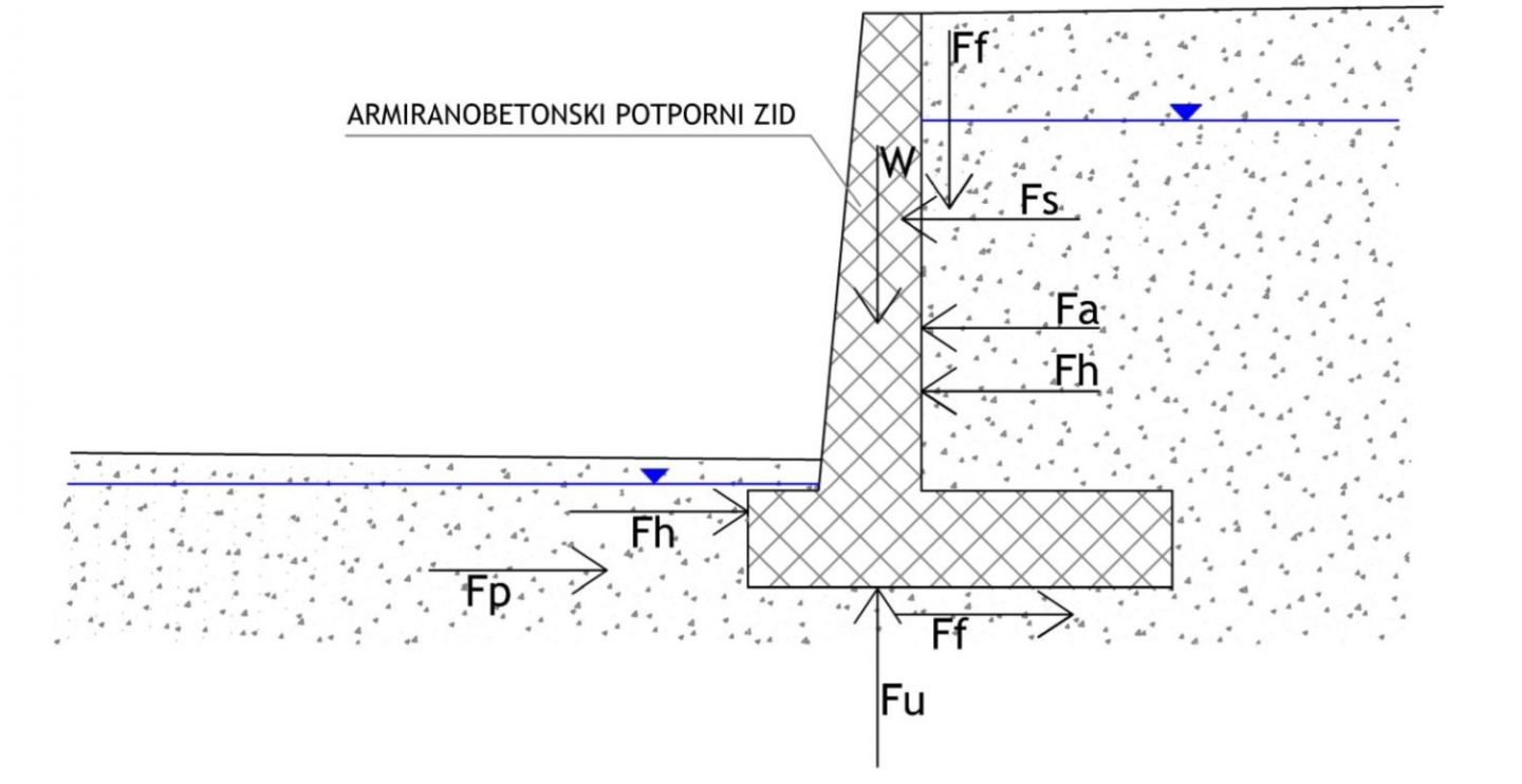
The forces acting on a retaining structure:
- Wall’s weight (W)
- Active pressure of the embankment and the soil behind the wall (Fa)
- Hydrostatic pressure (Fh)
- Hydrodynamic forces (Fu)
- Passive soil resistance in front of the footing (Fp)
- Soil reaction at foundation level (Ff)
- Seismically induced forces (Fs)
Wall’s weight is the wall volume multiplied by the wall material volume.
Active pressure is any load exerting pressure on a wall and trying to move it.
When the groundwater level is above the wall footing, hydrostatic pressure and hydrodynamic forces increase the total pressure on the wall and require stronger structures. In practice, different drainage systems are used to eliminate their effects.
The front of the reinforced concrete retaining wall is often embedded. Moving a wall in this zone results in an increase in pressures whose boundary magnitude is passive soil resistance.
For the determination of seismically induced forces, it is necessary to determine the earthquake area according to the seismological map of Croatia. The map offers earthquake strength information. The goal is to achieve a structured geometry that will ensure a uniform stress distribution on the elements affected by the earthquake.
Geometry of reinforced concrete retaining wall
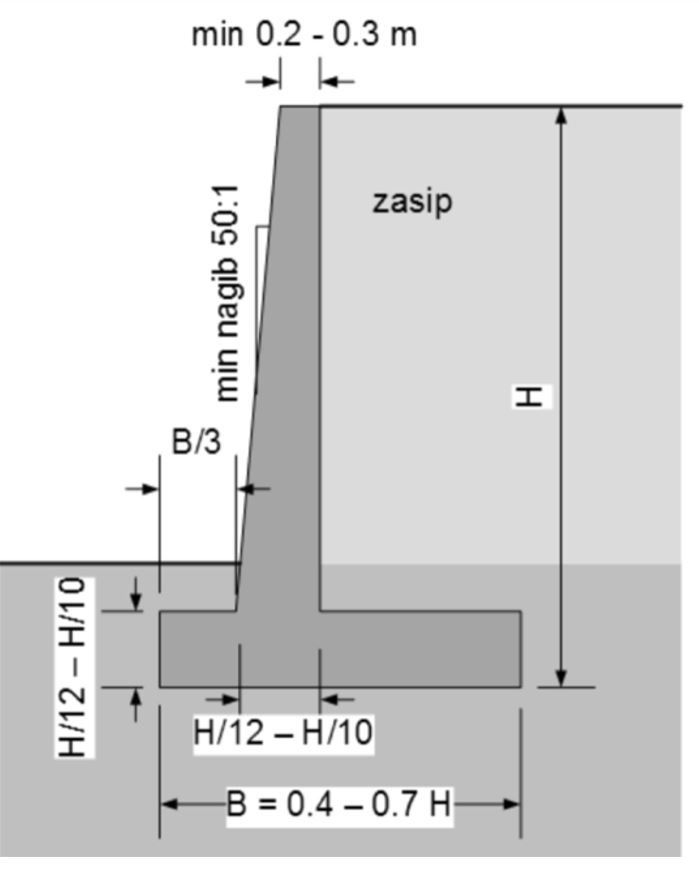
The shape of the reinforced concrete retaining wall looks like an inverted letter T or letter L. The basic shape of this wall is a reinforced concrete console clamped into a reinforced concrete plate. At greater heights, counter-forts are added in front of or behind a reinforced concrete retaining wall.
The wall stability, i.e. the required force balance, is achieved by designing the wall and the weight of the embankment on the foundation plate, which becomes an integral part of the structure. The active pressure load causes the maximum bending moment at the pinch point of the console in the base plate. Due to larger moments, a larger concrete section and the amount of reinforcement is required at this point.
When selecting the geometry of retaining structure, we start from the height, and the expected height from the top of the wall to the bottom of the foundation should be considered. It is also necessary to take into account the minimum depth of embedment, which should not be less than 50 cm or the minimum depth of foundation due to freezing.
The width of the wall, which can range from 0.4 to 0.7 H, is then selected. However, 0.5 H can be selected as the initial height, and increased or decreased as needed.
It is recommended to construct a jut in front of the wall, measuring at least 30 cm or H / 10. For the simplicity of construction, it is advisable that the rear face of the wall be vertical while the front one can be vertical or inclined. The minimum wall thickness in the top of the wall’s stem should be 20 cm.
After selecting the initial geometry, the calculation is made and, if necessary, the geometry is adjusted based on the obtained results.
Ultimate limit state calculation of reinforced concrete retaining wall
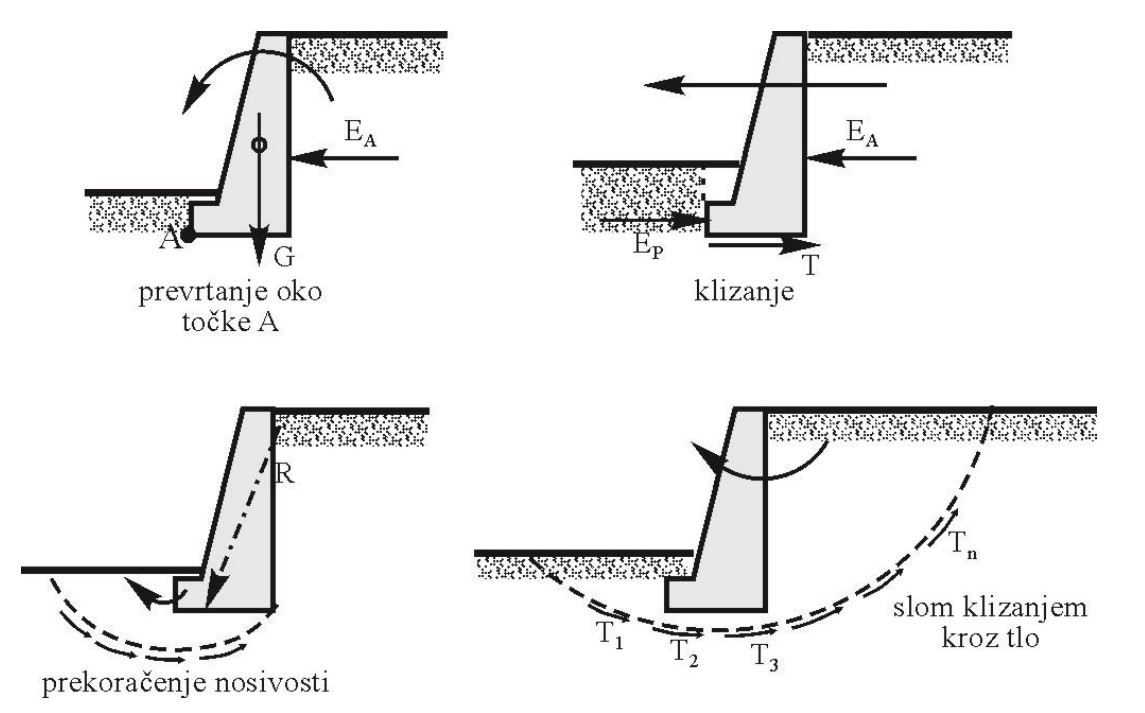
The retaining structures must be controlled for the ultimate limit state. The calculation purpose is to determine the safety factor (Fs) for each ultimate limit state. The safety factor should not be less than Fs = 1, which would mean that the observed system is not stable.
For reinforced concrete retaining structures, the following ultimate limit state conditions have to be considered:
- Toppling around point A
The toppling of the retaining wall is contradistinguished by the weight of the retaining wall itself and the passive resistance in front of the wall. - Loss of soil bearing capacity
The wall takes the loads on the back of the wall, as well as the friction between the wall and the soil. The design of a reinforced concrete retaining wall should ensure that the soil beneath the wall’s foundation can securely bear this load without collapsing. Therefore, the bearing capacity of the soil under the wall’s foundation should be checked. - Sliding failure
The retaining wall foundation must securely transfer the load of the wall into the soil foundation. There are two essential conditions for that. The first one is a satisfactory bearing capacity of the soil foundation. The second condition is the proper dimensioning of the reinforced concrete retaining wall foundation to prevent sliding. - Global stability
The retaining wall does not participate in the resistance to this boundary condition. A soil failure can affect the soil below, behind and in front of the retaining wall. Global stability is verified using slope stability check methods.
The approach to wall dimensioning depends on the loads (forces and moments acting on the concrete cross-section). It is necessary to check the limit of the concrete cross-section, both the foundation and the stem wall. Particular attention should be paid to the overlapping and reinforcement anchorage on the contact of foundation and wall stem. In high walls, it is possible to gradually reduce the stem wall thickness with height, i.e. to gradually reduce the thickness of the stem wall by lowering the moment to achieve savings in the amount of concrete.
An example of the reinforced concrete retaining wall with its characteristic profile and reinforcement is shown below:
Conclusion
When choosing a backfilled retaining structure, reinforced concrete console retaining walls are the most common choice nowadays.
They are also the simplest and the most economically acceptable retaining structure.
Some of the experience values and guidelines we have described above should be taken into account when choosing the geometry. For larger and more serious retaining structures, we recommend a more detailed check with an experienced designer.
Once there is a loss of load-bearing capacity of the retaining structure or its parts, remediation is very difficult.
If you have any questions, be free to contact us!
