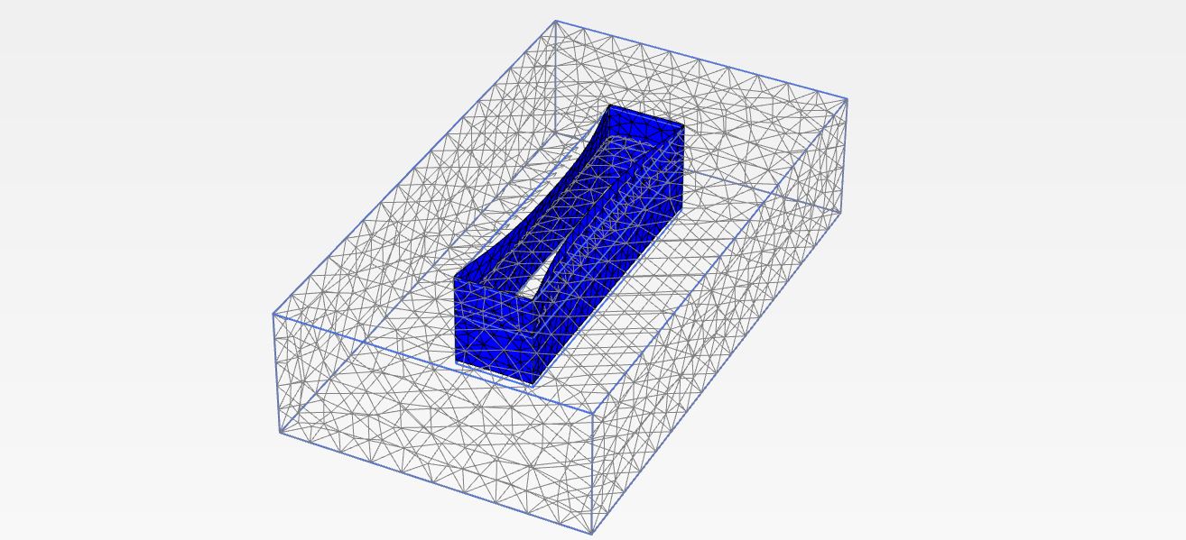
Corner effect in a building pit – comparison of 2D and 3D analysis
Design of the retaining structure (building pit) is important for choosing a reliable and cost-effective solution. This brings the necessity of a realistic calculation approach. Most of the computer programs for design of retaining structures are based on two-dimensional modeling. Two-dimensional (2D) plane-strain assumption is that section continues infinitely along the axis perpendicular to the section which is calculated.
With three-dimensional modeling, a more realistic calculation approach can be provided considering the variations of the soil layers, surcharge loads, topography and supporting conditions on the axis which is perpendicular to the calculated section.
This blog deals with the corner effects in which the retaining structures near building pit corners have stronger capabilities to resist deformation than those distant away as a result of spatial arching effects across the building pit corners. Contrary to the two-dimensional (2D) plane-strain assumption widely adopted in practice in which the displacements of retaining structure do not depend on the distance from building pit corner, most of the building pits exhibit corner effects. Because of the stiffening effects from the building pit corners, the minimum retaining structure displacements occur near the building pit corners and the maximum occurs at the longer span of the building pit.
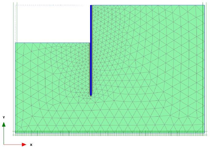
A comparison of the results of 2D and 3D modeling of the building pit was made using Plaxis 2D and Plaxis 3D software. Building pit dimensions of 10,0 x 40,0 m with an excavation depth of 5,0 m, retained with a diaphragm wall 12,0 m long and 0,50 m thick was calculated. Adopted soil parameters for calculation – bulk density γ=19,50 kN/m3, cohesion c=14,0 kN/m2, friction angle φ=25°, E50ref=10,0 MN/m2, Eoedref=10,0 MN/m2, Eurref=30,0 MN/m2 (hardening soil model).
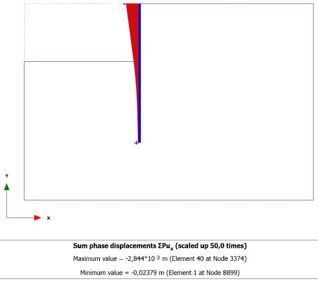
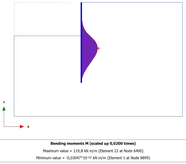
The calculation results obtained with Plaxis 2D software are shown below.
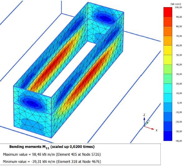
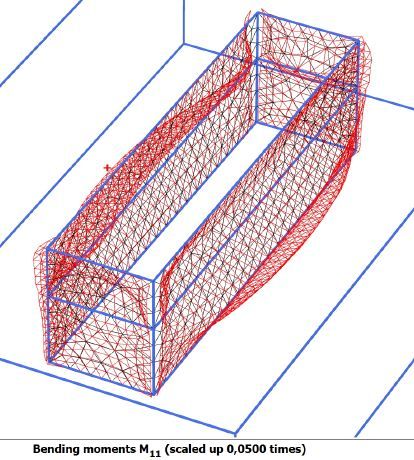
The calculation results obtained with Plaxis 3D software are shown below.
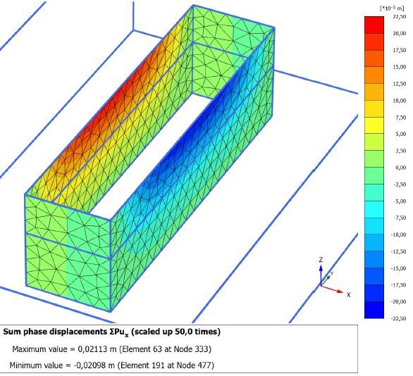
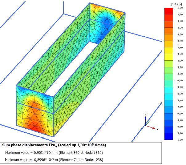
The maximum calculated horizontal displacement of the diaphragm wall obtained by Plaxis 2D is 24 mm, which is a higher value than 21 mm obtained by Plaxis 3D.
The maximum calculated bending moment of the diaphragm wall obtained by Plaxis 2D is 120 kNm, which is much higher value than 98,50 kNm obtained by Plaxis 3D. Horizontal displacements and bending moments of shorter span (10 m long) are significantly smaller than those of the longer span (40 m long) of the building pit. For shorter span bending moment of the diaphragm wall of 39,30 kNm and horizontal displacement of 1,0 mm were obtained by Plaxis 3D.
The maximum calculated bending moment of the diaphragm wall obtained by Plaxis 2D is 22% higher (120kNm vs 98kNm) than those obtained for a longer span and 305% higher (120kNm vs 39kNm) than those obtained for shorter span in Plaxis 3D. The maximum calculated horizontal displacement of the diaphragm wall obtained by Plaxis 2D is 14% higher (24mm vs 21mm) than those obtained for a longer span and 24 times higher (24mm vs 1mm) than those obtained for shorter span in Plaxis 3D.
Dimensioning of the retaining structure is performed on the basis of calculated displacements and internal forces and this determines the cost of geotechnical construction. It is recommended to perform 3D analysis on larger and more complex projects.
It can be concluded that the strengthening effect of the corner can lead to a significant reduction in retaining structure displacement and internal forces. The three-dimensional analysis offers a better prediction of ground movement than two-dimensional analysis. Because of the stiffening effects from the pit corners, the minimum retaining wall displacements occurred near the building pit corners and the maximum occurred at the middle of the longer span of the building pit. The retaining wall deformation decreases with decreasing distance from the corner.
